
Point-on-Wave Relay Replacement is an important part of maintaining reliable controlled switching in high-voltage electrical systems. A correctly applied controller helps a circuit breaker open or close at a calculated point on the voltage or current waveform, instead of operating at a random instant. This controlled timing can reduce electrical transients, limit unnecessary stress on primary equipment and support more stable system operation.
However, replacement is not simply a matter of removing an old relay and installing a new one. The controller, circuit breaker, wiring, operating times, protection philosophy and connected load all work together. A successful retrofit therefore requires careful engineering, disciplined site work and complete testing.
What Is Point-on-Wave Controlled Switching?
Point-on-Wave control, also known as controlled or synchronous switching, coordinates the opening or closing of individual circuit-breaker poles with selected points on the electrical waveform. The preferred switching instant depends on the application, the circuit-breaker characteristics and the type of equipment being energised or de-energised.
Engineers may apply controlled switching to transformers, capacitor banks, shunt reactors, cables, transmission lines and other high-voltage assets. Its purpose is not to replace the circuit breaker or the protection system. Instead, it adds a timing function that helps the breaker perform the requested switching operation under more favourable electrical conditions.
Without effective timing control, switching can produce high inrush current, temporary overvoltage, restrike or re-ignition risk, and additional mechanical or dielectric stress. The severity varies by system and application, but the underlying principle is consistent: the moment at which the contacts operate matters.
Why Point-on-Wave Relay Replacement Becomes Necessary
A controller can remain in service for many years, but age alone should not be the only trigger for replacement. Utilities and industrial operators should consider the complete condition and supportability of the controlled-switching scheme.
Common reasons to plan a replacement include:
- The existing controller is obsolete or no longer supported.
- Spare parts, engineering software or configuration tools are difficult to obtain.
- Alarms, event records or diagnostic functions have become unreliable.
- Breaker operating times have changed after maintenance or mechanism work.
- The control panel is being modernised and the existing device is no longer compatible with the revised scheme.
- Drawings, settings files or configuration backups are incomplete.
- Repeated troubleshooting is increasing maintenance effort or outage risk.
- The connected primary equipment or operating duty has changed.
These signs do not automatically prove that the controller has failed. They indicate that a structured engineering assessment is needed. Early planning is preferable to an urgent replacement during an unplanned outage.
Why Switching Timing Must Be Revalidated
A Point-on-Wave controller calculates when to issue each pole command so the breaker contacts reach their target position at the intended waveform point. That calculation depends on measured electrical signals, breaker operating characteristics, control-circuit delays and the configured switching strategy.
This means an old setting should not be copied into a replacement device without verification. Even when the primary circuit has not changed, breaker maintenance, coil condition, auxiliary relays, wiring changes, ambient conditions and mechanism wear can influence operating time.
Good replacement engineering reviews the complete timing chain. The goal is to confirm that the controller’s command, the breaker mechanism and the actual contact movement remain coordinated. Controlled switching is only effective when the installed system behaves as the configuration expects.
What a Professional Replacement Should Include
1. Existing-System Assessment

First, the work begins with a review of drawings, settings, event records, alarm history, switching duty and available breaker timing information. Engineers should identify every input, output, permissive, interlock, bypass and supervision signal associated with the existing scheme.
The assessment should also confirm the connected load and intended operating sequence. A transformer, reactor and capacitor bank do not necessarily use the same switching strategy.
2. Compatibility and Design Review
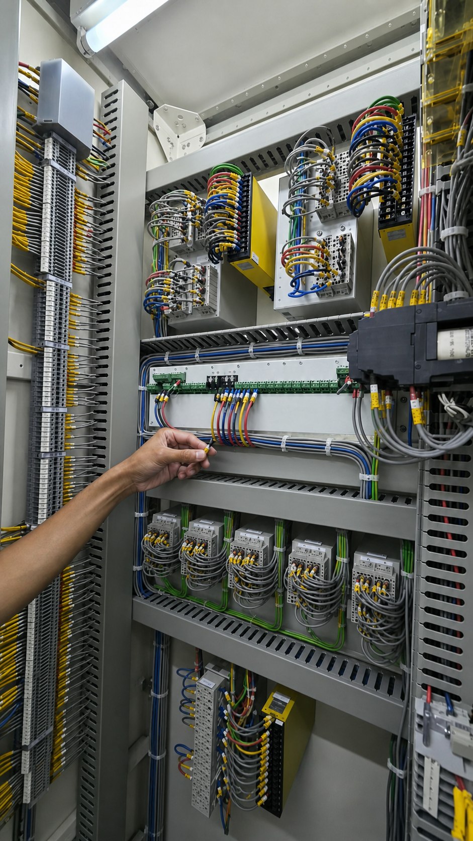
The replacement controller must be compatible with the available voltage and current signals, control supply, breaker interfaces, pole-operating arrangement and station communication requirements. Engineers should check existing terminal assignments and wiring against the new design instead of assuming equivalence.
In addition, where panel modifications are necessary, the design should consider access, heat dissipation, cable routing, segregation, labelling and future maintenance. A neat installation is more than a visual improvement. Clear routing and identification reduce testing time and lower the chance of wiring errors during later maintenance.
3. Safe Isolation and Controlled Installation

Site work should follow the approved outage, isolation and permit requirements. Before removing the existing controller, the team should verify the correct panel, prove isolation where required and preserve all available settings and records.
Panel cutting, drilling and cable work should protect nearby equipment from debris. The team should identify existing conductors before disconnection and check any modified wiring against the approved drawings. Temporary changes and bypasses must be controlled and formally cleared before return to service.
4. Configuration and Timing Data
Next, engineers should configure the new controller using validated system data and breaker operating characteristics. Depending on the application, this may include phase references, compensation values, mechanical operating-time information, adaptive timing functions, permissives and alarm thresholds.
Therefore, breaker timing data is especially important. If current measurements are unavailable or outdated, suitable timing tests may be needed to establish a reliable basis for the controlled-switching configuration.
5. Functional Testing and Commissioning
Commissioning should verify the complete signal path, not only the controller display. Typical checks may include power supply, voltage and current inputs, breaker commands, pole outputs, auxiliary contacts, alarms, interlocks, bypass functions, communication points and event recording.
For example, the test scope should match the scheme and site requirements. Where applicable, secondary injection, breaker timing measurements, sequence checks and controlled operational tests can confirm that the installed system responds as intended. The team should record and clear all temporary links, lifted wires and test modes before energisation. For further technical context, readers can review independent guidance on controlled switching commissioning and operation.
6. Documentation and Handover
Finally, a replacement is not complete until the documentation matches the installed condition. The handover package should store updated drawings, terminal schedules, settings files, test results, software backups and operating instructions in an accessible location.
As a result, clear handover information helps future teams understand normal indications, alarm response, bypass conditions and the process for reviewing switching events. This reduces dependence on individual memory and makes long-term maintenance more consistent.
Point-on-Wave Relay Replacement Benefits for Asset Owners
When properly engineered and commissioned, Point-on-Wave relay replacement can provide several practical benefits:
- Reduced transient stress: Controlled switching can limit avoidable inrush current and switching overvoltage for suitable applications.
- Improved equipment care: More favourable switching conditions can reduce electrical stress on breakers and connected primary assets.
- Better maintainability: A supported controller, current configuration tools and complete backups make future maintenance easier.
- Stronger diagnostics: Reliable event records and alarm information help engineers investigate abnormal operations more efficiently.
- Lower obsolescence risk: Planned replacement reduces exposure to unavailable spares and unsupported software.
- More predictable outage work: A documented retrofit plan allows design, wiring, testing and commissioning activities to be coordinated before the outage begins.
- Improved lifecycle visibility: Updated drawings, settings and timing records establish a clearer baseline for future condition assessment.
The value is not created by the controller alone. It comes from integrating the device correctly with the breaker, control circuits and operating requirements.
Point-on-Wave Relay Replacement Mistakes to Avoid
However, several shortcuts can weaken an otherwise well-planned retrofit:
- Treating the replacement as a purely like-for-like hardware change.
- Reusing legacy settings without validating breaker timing and system conditions.
- Overlooking bypass, interlock or supervision logic.
- Making undocumented wiring changes during the outage.
- Testing individual inputs and outputs without checking the full operating sequence.
- Returning the scheme to service without verified backups and updated drawings.
- Assuming that a successful command proves optimum point-on-wave operation.
Therefore, a disciplined test plan should show how each important function will be verified and what evidence will be retained.
Frequently Asked Questions
Is a Point-on-Wave relay the same as a protection relay?
No. A Point-on-Wave controller coordinates circuit-breaker operating timing. Protection relays detect abnormal electrical conditions and initiate protective actions. The functions can interact, but their primary purposes are different.
Does replacing the controller require a new circuit breaker?
Not always. A retrofit may be possible when the existing breaker, pole-operating arrangement, signals and control circuits are suitable. Compatibility and breaker timing must be assessed before the design is finalised.
Which equipment can benefit from controlled switching?
Applications commonly include transformers, capacitor banks, shunt reactors, cables and transmission lines. The appropriate strategy depends on the equipment and power-system conditions.
Can the old settings be copied to the new controller?
Legacy settings are useful reference information, but they should be reviewed and validated. Breaker operating characteristics, wiring, control delays and the replacement controller’s configuration method may differ.
How is a replacement tested?
Testing normally covers electrical inputs, commands, pole outputs, auxiliary contacts, alarms, interlocks, bypass functions, event records and relevant communication signals. Breaker timing and operational sequence checks may also be required, depending on the application.
Plan the Retrofit Around the Complete Switching Scheme
Point-on-Wave relay replacement is most effective when it is treated as a controlled-switching system upgrade rather than a device swap. The right approach combines engineering review, accurate breaker data, careful panel work, technically plausible wiring, thorough testing and complete documentation.
Organisations planning a controlled-switching upgrade should begin with an assessment of the existing scheme and its records. A clear scope developed before the outage can reduce uncertainty, support safer execution and improve confidence in the final result.
Learn more about our electrical engineering and automation services or contact our engineering team to discuss a controlled-switching assessment.